Clack-BASIC Compiler & 16-Bit Relay Architecture
High-precision three-address code (3AC) intermediate compilation, bitwise arithmetic, and hardware-tailored clock cycles for Peter's spectacular 16-Bit Relay Computer.
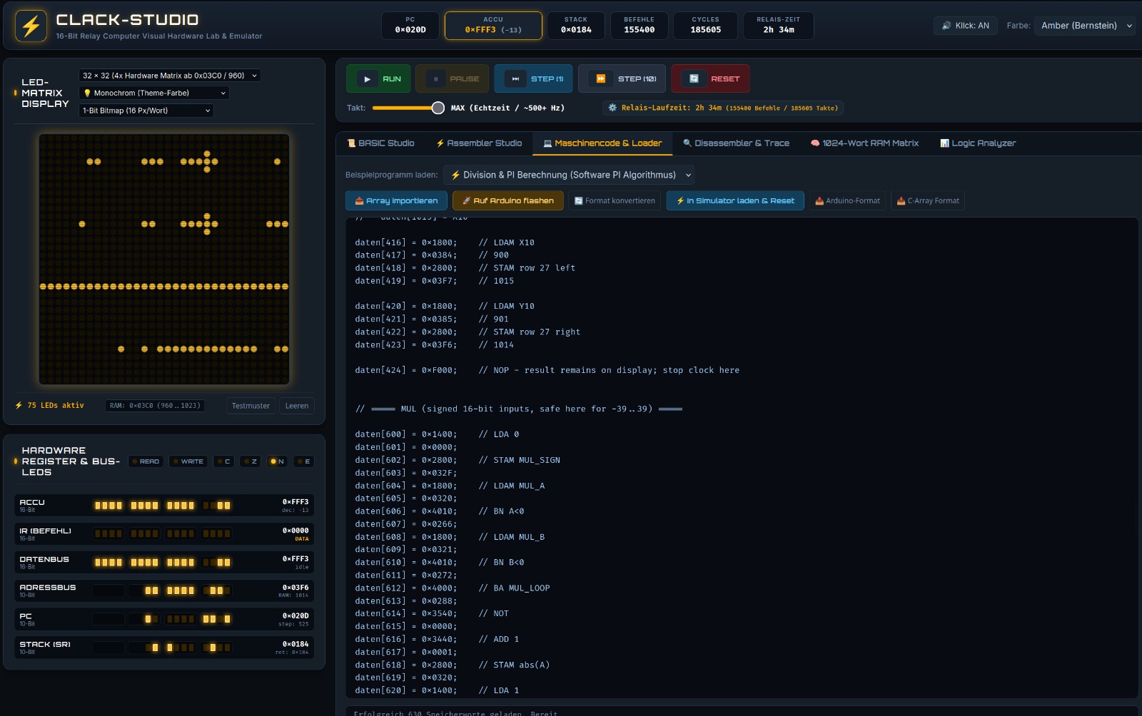
The computer designed and built by Peter operates completely with mechanical weak-current relays for registers and sequencer control, coupled with diode matrices for arithmetic and logic functions. Clock cycles are physically bounded by relay reed inertia (~8–12 ms pull-in, ~4–6 ms drop-out) and electromechanical contact bounce.
⚙️ Register Architecture
The CPU features four primary 16-bit registers and a condition code register for conditional branching:
ACC(Accumulator): Primary execution register for ALU operations and I/O transfers.B(Auxiliary Register): Secondary operand buffer for arithmetic and logic functions.PC(Program Counter): Points to the current instruction address within the 1024-word memory.SP(Stack Pointer): Addresses the hardware call stack descending from0x037Fdownwards.FLAGS: Relay-driven condition latches: Zero (Z), Carry (C), Sign (S), and Overflow (O).
⏱️ Relay Dynamics & Contact Debounce
Mechanical contacts oscillate for several milliseconds upon closure. Clock timing protects the ALU from transitional noise:
- Pull-in Latency: 8–12 ms until electrical contact is securely established.
- Contact Bounce: 1.5–3 ms reed oscillation suppressed with snubber diodes.
- Gated Sampling Window: Bus latching is only enabled after the debounce monostable settles.
- Clock Rate: ~15–30 Hz on physical relays; accelerated up to 10,000 Hz in the emulator.
Memory Allocation Map (1024 Words à 16 Bit)
| Address Range (Hex) | Address Range (Decimal) | Block Size | Functional Assignment | Bus Access |
|---|---|---|---|---|
0x0000 – 0x001F |
0 – 31 | 32 words | Zero-Page: Fast direct variables (A–Z), system state registers, intermediate scratchpads | Read / Write (1 cycle) |
0x0020 – 0x02FF |
32 – 767 | 736 words | Program Code & Bytecode: Compiled Clack-BASIC three-address instructions | Execute / Read |
0x0300 – 0x037F |
768 – 895 | 128 words | Hardware Call-Stack: Return addresses for GOSUB / RETURN and local pushed data |
LIFO Stack (descends from 0x037F) |
0x0380 – 0x03BF |
896 – 959 | 64 words | 32×32 Relay-Matrix Framebuffer: 64 words à 16 bit = 1024 individual relay display pixels | Direct access via PSET / LINE / CLS |
0x03C0 – 0x03FF |
960 – 1023 | 64 words | Hardware I/O & Controller: Serial UART bridge, keyboard FIFO buffer, FPGA interface | Memory-Mapped I/O |
Clack-BASIC compiles clean Dartmouth BASIC dialect directly into optimized 16-bit Three-Address Code (3AC) and relay machine binaries. Variables are stored as 16-bit signed integers (-32768 to 32767).
| Statement / Syntax | Category | Description & Hardware Mapping |
|---|---|---|
A = 42 / DIM X(10) |
Variables | 16-bit signed integers (-32768 to 32767). Arrays are allocated contiguously in high memory. |
IF A > B THEN ... ELSE ... |
Control Flow | Comparison evaluates via ALU flags (CMP). Conditional jumps branch via JZ, JNZ, JGT, JLT. |
FOR I = 1 TO 10 STEP 2 ... NEXT |
Loops | Hardware-optimized loop counters bound directly to register or Zero-Page addresses. |
GOSUB 500 ... RETURN |
Subroutines | Pushes current Program Counter onto the hardware stack (0x0300–0x037F) and branches. |
WHILE X > 0 ... WEND |
Loops | Pre-condition evaluated loop with check executed before each iteration. |
DATA 10, 20, 30 |
Data Tables | Defines a static constant table in program memory for sequential streaming into variables. |
READ A, B, C |
Data Tables | Reads sequential constants from the active DATA bank and advances the internal read pointer. |
RESTORE |
Data Tables | Resets the internal DATA pointer back to the beginning of the first DATA statement. |
STOP |
Debugging | Programmed Breakpoint: Halts CPU execution, yielding control back to the debugger to inspect registers and memory. |
SQR(X) NEW v1.5.5 |
Arithmetic | Integer Square Root: 8-iteration division-free shift-and-subtract algorithm in ≤16 clock cycles. |
SQR(X, DEC) NEW v1.5.5 |
Arithmetic | Fixed-Point Square Root: Computes square roots with up to 2 decimal places (e.g. SQR(2, 2) → 141 = 1.41) without division. |
CLS |
Matrix Graphics | Clears the 32×32 relay matrix by rapidly writing 0 to all 64 framebuffer words. |
PSET(X, Y, C) |
Matrix Graphics | Sets (C=1) or clears (C=0) the individual LED pixel at coordinates (X, Y) in the range 0–31. |
LINE(X1, Y1, X2, Y2, C) |
Matrix Graphics | Draws a continuous line using integer-only Bresenham rasterization directly on the relay display. |
PIXELMOVE(DIR) |
Matrix Graphics | Hardware-accelerated viewport scroll of the 32×32 display (DIR: 1=Up, 2=Down, 3=Left, 4=Right). |
POKE Addr, Val / PEEK(Addr) |
Direct Memory | Direct 16-bit word read and write access to any physical memory address on the relay computer. |
📐 Technical Deep-Dive: Division-Free Square Root in v1.5.5
Because integer division on an electromechanical relay CPU takes up to 32 cycles of audible relay clicking, Clack-BASIC v1.5.5 computes square roots using an 8-iteration division-free shift-and-subtract bitwise algorithm. For 16-bit integers, execution is deterministic and finishes in exactly 8 bit stages:
10 REM ========================================================
20 REM CLACK-BASIC v1.5.5 SQR DEMO // 16-BIT RELAY COMPUTER
30 REM ========================================================
40 CLS
50 PRINT "TEST 1: INTEGER ROOTS"
60 FOR X = 1 TO 10
70   Y = SQR(X * X)
80   PRINT "SQRT("; X * X; ") = "; Y
90 NEXT X
100 PRINT "----------------------------------------"
110 PRINT "TEST 2: HIGH-PRECISION FIXED-POINT ROOT"
120 REM SQR(2, 2) computes sqrt(2) with 2 decimal digits (scaled by 100)
130 F = SQR(2, 2)
140 W_INT = F / 100
150 W_DEC = F MOD 100
160 PRINT "SQRT(2) = "; W_INT; "."; W_DEC; " (RESULT: 1.41)"
170 END
The machine architecture executes fixed 16-bit opcodes. Each cycle corresponds to a complete mechanical relay switching phase:
| Opcode (Hex) | Mnemonic | Operand | RTL Execution (Micro-Operations) | Cycles (Latency) |
|---|---|---|---|---|
0x00 | NOP | - | No Operation (Bus idle) | 1 (~15 ms) |
0x01 | LOAD | [addr] | ACC ← Mem[addr] | 2 (~30 ms) |
0x02 | STORE | [addr] | Mem[addr] ← ACC | 2 (~30 ms) |
0x03 | LOADI | #val | ACC ← Immediate 16-Bit Value | 1 (~15 ms) |
0x04 | ADD | [addr] | ACC ← ACC + Mem[addr], Flags updated | 2 (~30 ms) |
0x05 | SUB | [addr] | ACC ← ACC - Mem[addr], Flags updated | 2 (~30 ms) |
0x06 | CMP | [addr] | Flags ← ACC - Mem[addr] (ACC unchanged) | 2 (~30 ms) |
0x07 | JMP | addr | PC ← addr | 1 (~15 ms) |
0x08 | JZ | addr | IF Z=1 THEN PC ← addr | 1 (~15 ms) |
0x09 | JNZ | addr | IF Z=0 THEN PC ← addr | 1 (~15 ms) |
0x0A | CALL | addr | PUSH PC; PC ← addr | 3 (~45 ms) |
0x0B | RET | - | POP PC | 2 (~30 ms) |
0x0C | OUT | port | Port[port] ← ACC | 1 (~15 ms) |
0x0D | IN | port | ACC ← Port[port] | 1 (~15 ms) |
0x1F | HALT | - | Stop clock generator, de-energize relays to idle | 1 |
🌌 1. Mandelbrot Fractal on 32×32 Relay Matrix
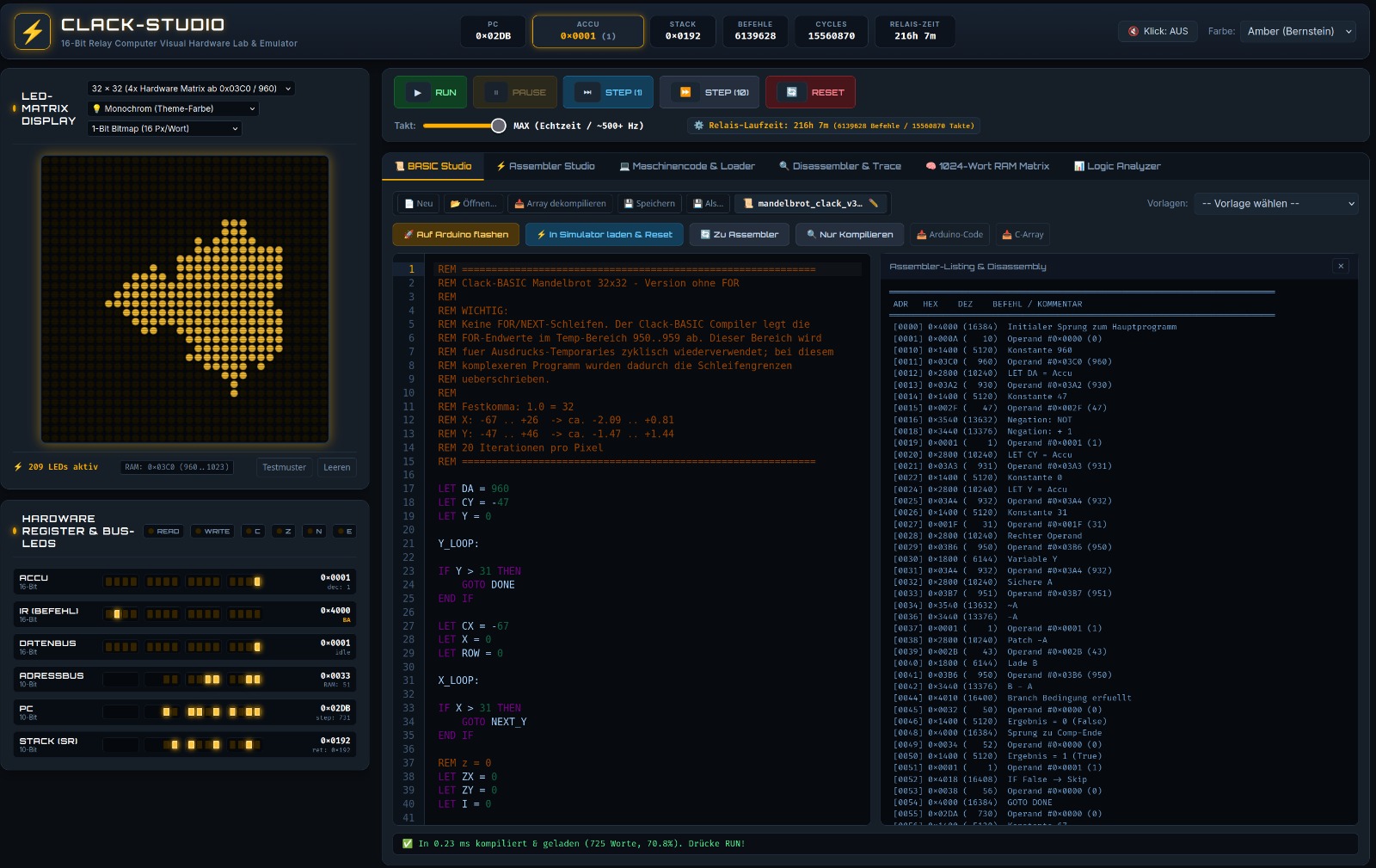
This program executes natively on Peter's physical 16-bit relay computer! It calculates the Mandelbrot set using 16-bit fixed-point arithmetic (scaling factor 256 = 1.0) and drives the electromechanical relays of the 32×32 LED matrix display.
10 REM ========================================================
20 REM MANDELBROT SET 32x32 FOR PETER'S RELAY COMPUTER
30 REM 16-Bit Fixed-Point Arithmetic (Scaling: 256 = 1.0)
40 REM ========================================================
50 CLS
60 MAXITER = 16
70 FOR Y = 0 TO 31
80   CI = (Y - 16) * 16
90   FOR X = 0 TO 31
100    CR = (X - 22) * 16
110    ZR = 0
120    ZI = 0
130    FOR I = 1 TO MAXITER
140      ZR2 = (ZR * ZR) / 256
150      ZI2 = (ZI * ZI) / 256
160      IF (ZR2 + ZI2) > 1024 THEN GOTO 220
170      ZI = (ZR * ZI) / 128 + CI
180      ZR = ZR2 - ZI2 + CR
190    NEXT I
200    PSET(X, Y, 1)
210    GOTO 230
220    PSET(X, Y, 0)
230  NEXT X
240 NEXT Y
250 END
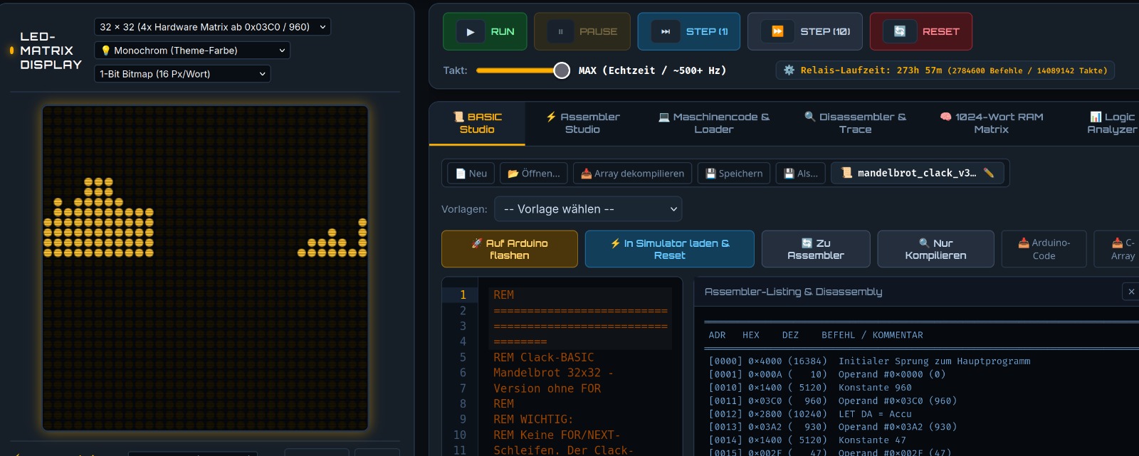
The photograph shows the original LED matrix display of the relay computer after running the Mandelbrot calculation above. The distinctive cardioid and bulb geometry is sharply defined across the 1024 relay pixels!
📊 2. Data Tables & Breakpoints: DATA, READ, RESTORE & STOP
Demonstrates sequential constant streaming from program memory and the programmed hardware breakpoint (STOP) for cycle-level register and stack inspection.
10 REM ========================================================
20 REM CLACK-BASIC: DATA, READ, RESTORE & STOP DEMO
30 REM ========================================================
40 CLS
50 PRINT "STREAMING DATA TABLE:"
60 FOR I = 1 TO 4
70   READ V
80   PRINT "VALUE "; I; " = "; V
90 NEXT I
100 PRINT "PROGRAMMED BREAKPOINT (STOP)..."
110 STOP : REM CPU execution halts here; registers can be inspected!
120 PRINT "RESETTING DATA POINTER (RESTORE)..."
130 RESTORE
140 READ FIRST_VAL
150 PRINT "FIRST VALUE RE-READ: "; FIRST_VAL
160 DATA 100, 250, 42, 888
170 END
💻 Clack CLI Quickstart Guide
Once downloaded, the compiler toolchain can be executed directly in your terminal:
# Grant executable permissions (Linux / macOS)
chmod +x clack-linux-amd64

# Compile BASIC source file into relay machine binary
./clack-linux-amd64 build mandelbrot.bas -o mandelbrot.bin

# Execute program directly in the virtual 16-bit relay emulator
./clack-linux-amd64 run mandelbrot.bas

# Disassemble binary machine code back to assembly mnemonics
./clack-linux-amd64 disasm mandelbrot.bin